




CALIBRATION WALKTHROUGH
Step by step configuration and initial setup guide
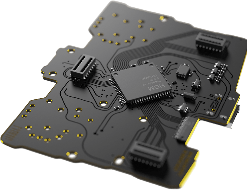
Table of Contents
Follow the guides below to set up, calibrate, and fine-tune your controller.
1. Initial Setup
Connect your controller and complete the first-time calibration.
2. Calibration & Settings
Learn what every calibration option does and how to configure your controller.
3. Circularity & Error Rate
Understand circularity, error rate, and how they affect your aiming precision.
4. Advanced Circularity Tuning
Learn when and when not to adjust circularity for your playstyle.
AIM In-House Settings
See the recommended settings used by the AIM Controllers team.
AIM MH5 SETUP GUIDE
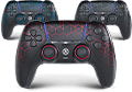
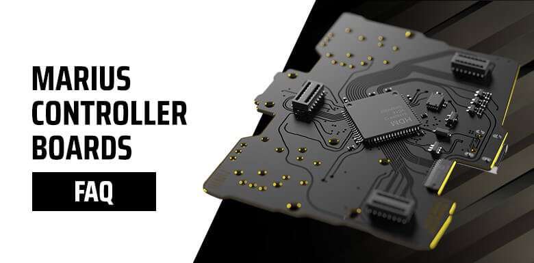
The AIM MH5 Controller is powered by the Marius Board and gives you complete control over your controller with advanced calibration and customization tools.
This guide will walk you through the initial setup, calibration, and every available setting step by step.
Need help? Simply follow each guide below in order.
BEFORE PROCEEDING
Before You Begin
Every AIM MH5 Controller is professionally assembled, tested, and calibrated before shipping. For many players, the default settings will already provide an excellent experience.
However, every player is different. The Marius Board gives you complete control over calibration, allowing you to fine-tune your controller to match your own preferences.
Don’t worry about experimenting. You can always repeat the Initial Setup to restore or recalibrate your controller at any time.
Important Information
Do not overclock your controller. The Marius Board already supports native 8000Hz polling.
Using overclocking tools such as HIDUSBF is unnecessary and may reduce performance or cause unexpected issues. For the best performance, always connect your controller directly to a rear USB port using a USB-A to USB-C data cable.
Features Not Supported
Controllers built with the Marius Board are designed exclusively for competitive PC gaming and therefore do not support:
- ▪ Console connectivity
- ▪ Bluetooth / Wireless mode
- ▪ Macros or keybinding
- ▪ Rumble / Vibration
- ▪ Touchpad gestures
- ▪ Internal battery operation
- ▪ Gyroscope / Motion controls
- ▪ Headphone jack
- ▪ Reset button functionality
Marius Board Setup
Follow these steps before starting calibration.
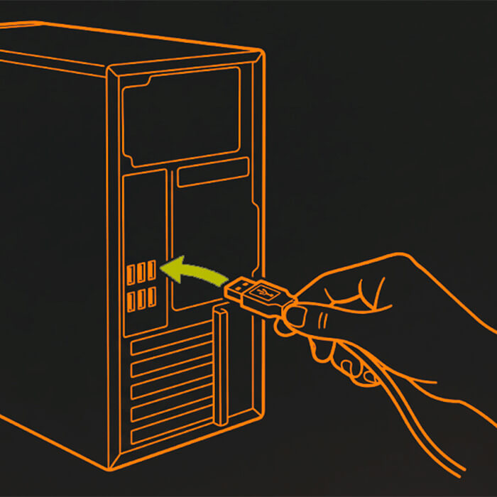
Step 1: USB-A → PC
Connect the USB-A end of the cable directly to a rear USB port on your PC. Avoid front panel USB ports and USB hubs.
For the best experience, use a high-quality USB-A to USB-C data cable (USB 2.0 or newer).
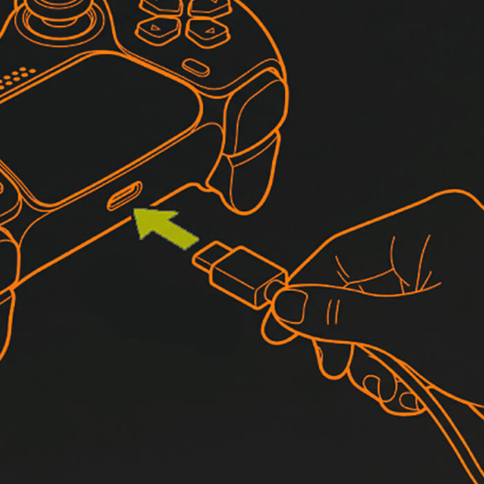
Step 2: USB-C → Controller
First, open the official setup tool website: devsetup.mariusheier.com
Press and hold the PS Button on your controller. While holding it, plug the USB-C cable into your controller.
When Setup Mode is active, the LED will slowly cycle between red, white and blue.
If the LED flashes green, update your controller firmware first at: update.mariusheier.com. Still can’t enter Setup Mode? Contact Customer Support.
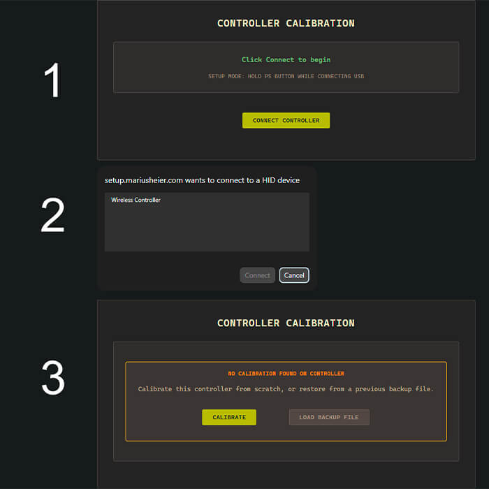
STEP 3: Connect your Controller
Click the CONNECT CONTROLLER (A) button. This will pop up a browser window. Select your controller from the list, then click Connect (B).
Next, read the on-screen instructions. When you’re ready to proceed, click I’M READY – START CALIBRATION (C).
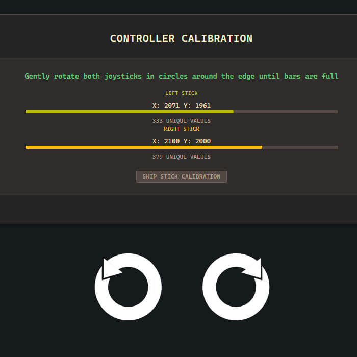
Step 4: Thumbstick Calibration
Rotate both thumbsticks around their full range in both directions. Keep rotating until both progress bars are completely full. The next step will begin automatically.
Use firm but gentle pressure. Pressing too lightly or too hard against the thumbstick gate may reduce calibration accuracy.
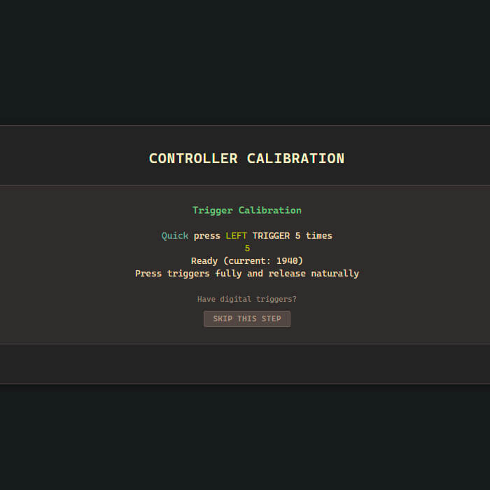
Step 5A: Trigger Calibration (1/3)
Quickly press and fully release the Left Trigger. Repeat until the software automatically advances.
Do not press SKIP THIS STEP. If skipped accidentally, rerun the Initial Setup or select Analog → Recalibrate Triggers from the Settings page after setup.
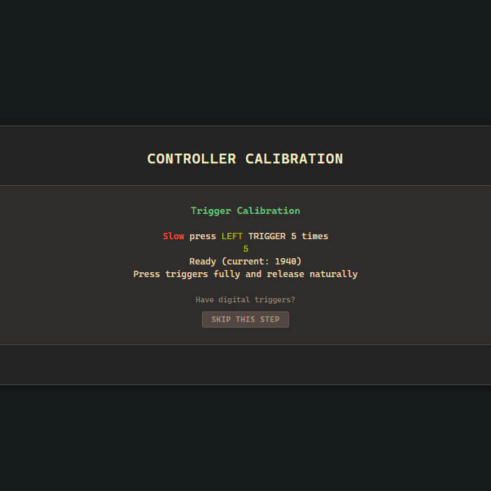
Step 5B – Trigger Calibration (2/3)
Slowly press and release the Left Trigger. Repeat until the software accepts the movement.
Smart Triggers have almost no travel, making this step harder. Treat the “slow press” as a slightly longer press until it registers.
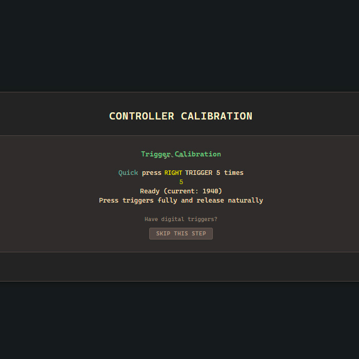
STEP 5C: Trigger Calibration (3/3)
Repeat the previous trigger calibration steps for the Right Trigger (Quick press/release, then Slow press/release).
Once finished, you’ll be taken directly to the Calibration & Settings page.
Calibration & Settings
Customize and fine-tune how your sticks and triggers behave.
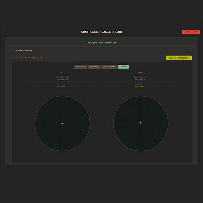
Stick Configuration (1/3)
This page lets you customize how your thumbsticks behave. Adjust the maximum input range of each thumbstick to fine-tune its response.
Over time, every thumbstick naturally settles slightly away from its original center position. If this causes unwanted stick drift, Quick Recenter automatically recenters the resting position without changing your other settings.
For a detailed explanation of Circularity, Circularity Error Rate (CER), and advanced calibration, see the “Circularity, Error Rates & You” guide.
Stick Configuration (2/3)
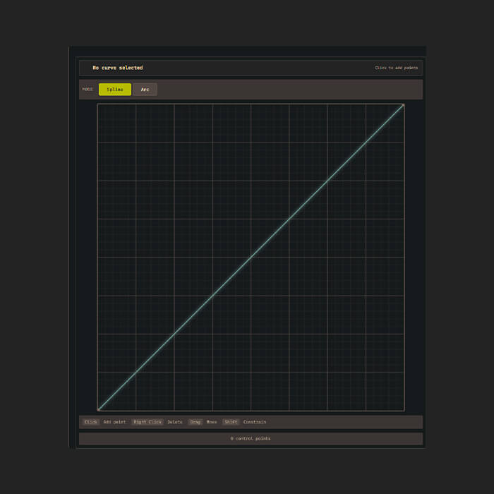
Adjust how your controller responds throughout the thumbstick’s movement. Different response curves can make aiming feel faster, smoother, or more precise depending on your playstyle.
Controller response curves and in-game response curves are independent. Using both at the same time may produce unexpected results. For the most consistent experience, avoid applying multiple response curves simultaneously.
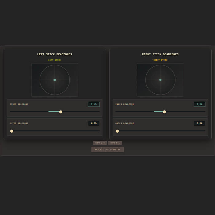
Stick Configuration (3/3)
Deadzones determine when thumbstick movement begins and ends. Inner Deadzone helps eliminate unwanted movement caused by minor stick drift. Outer Deadzone controls how quickly your controller reaches maximum input, which can help with movement mechanics in games such as Call of Duty.
Deadzones configured here work independently from your game’s deadzone settings. If both are adjusted, their effects may combine. Experiment with different values until you find the response that feels best for your playstyle.
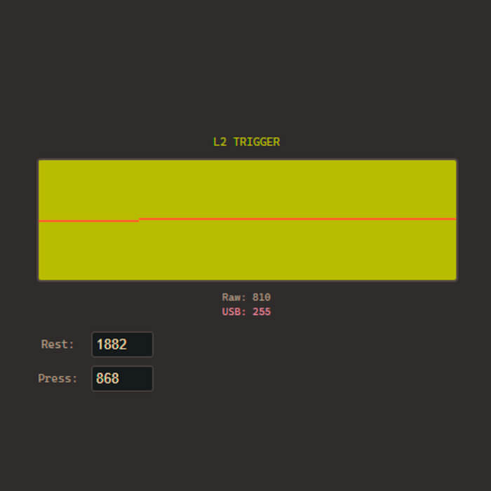
REST VALUE
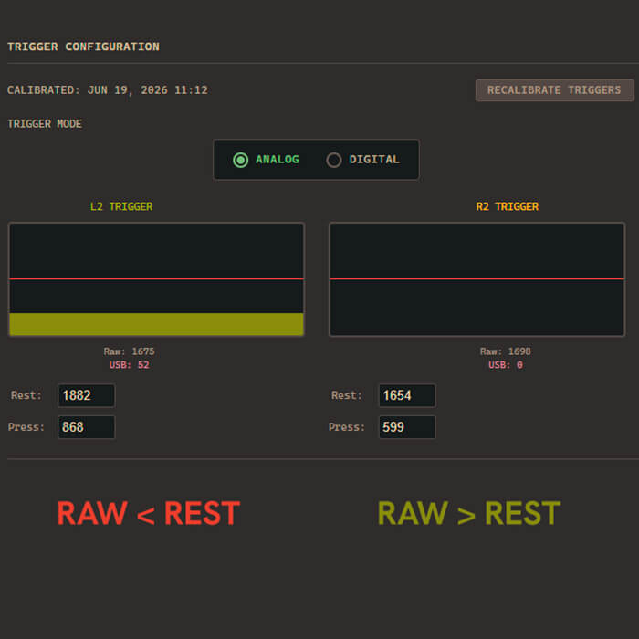
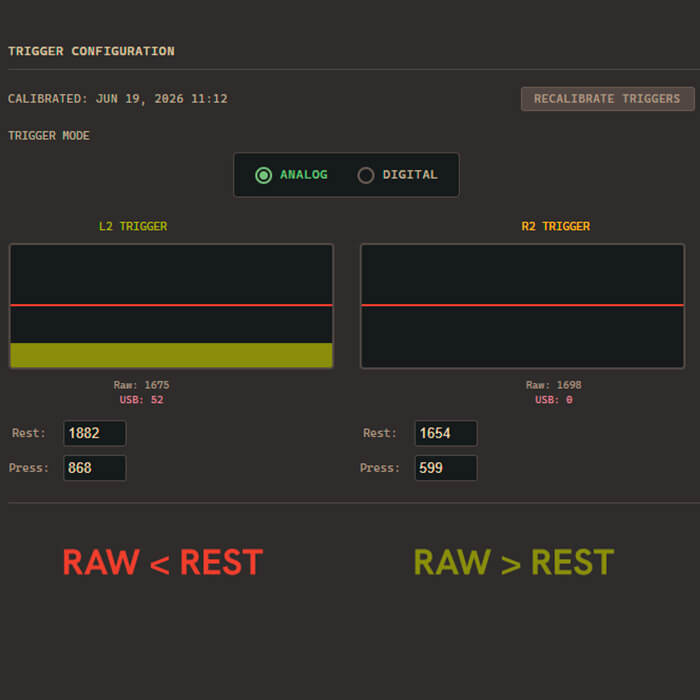
If your triggers don’t behave as expected after the initial calibration, you can fine-tune them here. The Raw value shows the live trigger input reported by the controller. When the trigger is fully released, the Raw value should always be higher than the REST value. If it isn’t, adjust the REST value until the trigger rests correctly.
REST VALUE
If the Raw value is lower than the REST value, the trigger may activate even when untouched. Reduce the REST value in small steps (20 – 50) until the trigger no longer registers input at rest.
The difference between Raw and REST affects trigger sensitivity. A larger gap requires more pressure before the trigger activates. A smaller gap makes the trigger activate sooner. A difference of 100 – 150 is a good starting point for most players.
PRESS VALUE
The PRESS value controls how much force is required for the trigger to reach maximum input. If pressing the trigger fully doesn’t fill the meter, increase the PRESS value in small steps until both triggers consistently reach 100%.
Setting the PRESS value too high may cause the trigger to reach maximum input earlier than intended. Most players won’t notice a difference, but games that rely on gradual trigger input may feel less precise.
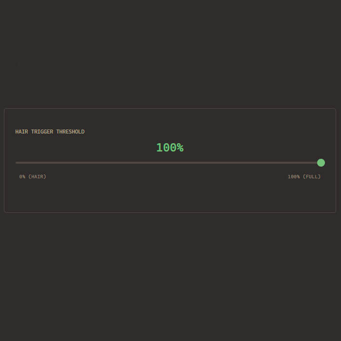
HAIR TRIGGER THRESHOLD
For the most consistent performance, leave Hair Trigger Threshold set to 100%. This setting is not required for normal use and changing it is not recommended.
Final Sections
Complete your configuration, map your inputs, and save your profile.
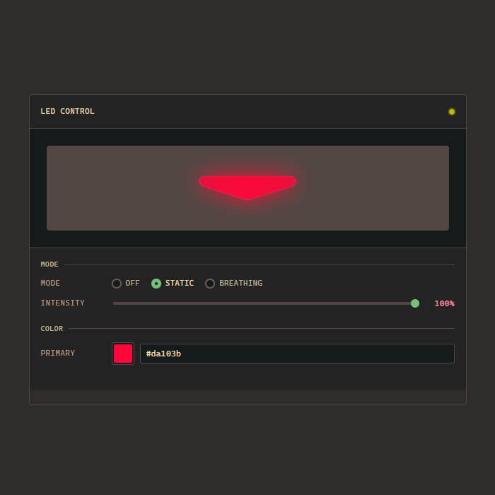
LED Control
Customize your controller’s LED by changing the color, brightness, and lighting effect.
Every AIM MH5 Controller ships with our default LED configuration, but you’re free to personalize it however you like.
Changes only affect the controller’s appearance and have no impact on performance.
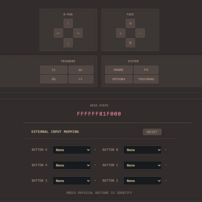
Rear Button Mapping
Configure your rear buttons using the Marius Controller Setup Tool: devsetup.mariusheier.com
Press a rear button on your controller to identify it in the software, then assign any supported controller input. You can remap any rear button to match your preferred layout and save the changes directly to your controller.
Left Upper → △ Triangle
Left Lower → ✕ Cross
Right Upper → □ Square
Right Lower → ◯ Circle
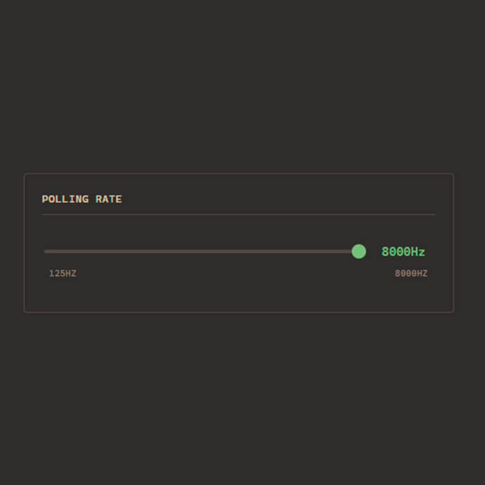
Polling Rate
Drag the slider to select your preferred polling rate. For the lowest possible input latency, we recommend using 8000Hz.
Some PCs, USB controllers, or individual games may not perform optimally at 8000Hz. If you experience stuttering, instability, or reduced performance, try 4000Hz or 2000Hz instead.
Even at lower polling rates, you’ll still benefit from the Marius Board’s low-latency architecture.
Save Your Configuration
When you’re finished, click SAVE TO CONTROLLER. The software will verify your settings and write them directly to the controller.
Once Configuration applied successfully appears, unplug and reconnect your controller before testing it in-game.
You’re all set. Enjoy your AIM MH5 Controller.
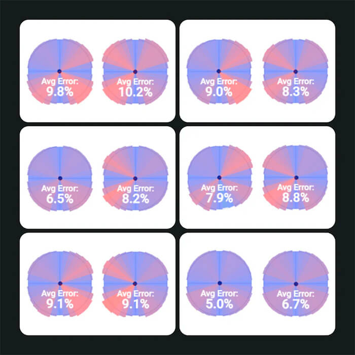
Circularity, Error Rates, and You
Now that your controller is calibrated, it’s time to understand one of the most important thumbstick settings: Circularity Error Rate (CER).
When you test Circularity, the software measures your thumbstick’s full range of motion and compares it to a perfect circle. The difference between those two shapes is called the Circularity Error Rate (CER).
The short version
CER measures how closely your thumbstick follows a circular movement. Higher or lower isn’t automatically better—it depends on how games interpret controller input.
Most games are designed around the behavior of standard OEM controllers rather than mathematically perfect circles. Because of this, an extremely low CER isn’t always ideal.
Likewise, a very high CER can make diagonal movement behave differently from cardinal directions. The goal isn’t to achieve the lowest possible number—it’s to find a range that delivers smooth and consistent gameplay.
Understanding the examples
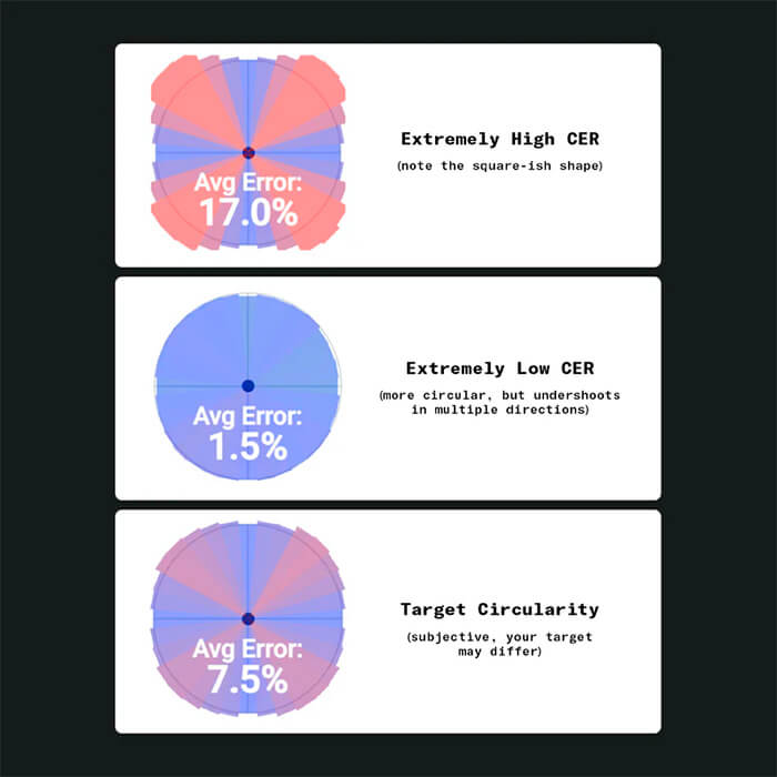
High CER (~15 – 20%)
- • Diagonals extend farther than expected.
- • The movement shape becomes more square.
- • Some older games may actually benefit from this behavior.
Low CER (~0 – 2%)
- • Movement stays very close to a perfect circle.
- • Some games may not receive the full analog range they expect.
- • This can occasionally affect mechanics such as sprinting or analog movement.
Recommended Range
For most modern games, a CER between 6% and 9% provides the best balance between accuracy and compatibility.
If your controller already falls within this range, no adjustment is usually necessary. If not, continue to the next guide to learn how to fine-tune it.
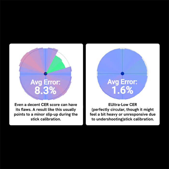
Adjusting Circularity Error Rate
After completing setup, check your controller’s Circularity using Gamepad Tester.
- • Connect your controller.
- • Open Gamepad Tester: hardwaretester.com/gamepad
- • Enable Test Circularity.
- • Compare your results with the examples below.
If your controller already performs well in-game, no adjustment may be necessary.
Fixing Low Circularity Error Rate (Sluggish Movement)
Green areas indicate that part of the thumbstick’s movement isn’t reaching its full range. This can reduce movement accuracy and may affect gameplay.
An extremely low Circularity Error Rate (CER) isn’t always ideal. If parts of the movement fall short of the expected range, you may notice:
Potential Issues
If your Circularity test shows undershooting, you might experience the following behaviors during gameplay:
- ▪ Reduced movement speed in certain directions.
- ▪ Inconsistent analog response.
- ▪ Sprinting or movement mechanics that don’t trigger reliably in some games.
If you notice these symptoms, recalibrate the thumbsticks or adjust the circularity settings until the full range is reached.
Identifying Issues (1/3)
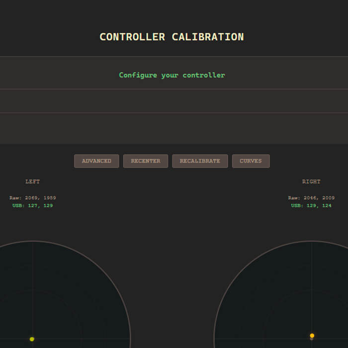
If your Circularity test shows undershooting, start by recalibrating your controller using the Setup tool and test again.
Many Circularity issues are resolved with a proper recalibration.
If the problem remains, note which directions are affected before continuing.
Identifying Issues (2/3)
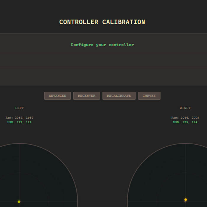
Reconnect your controller and return to Stick Configuration.
Click Advanced to enable fine-tuning.
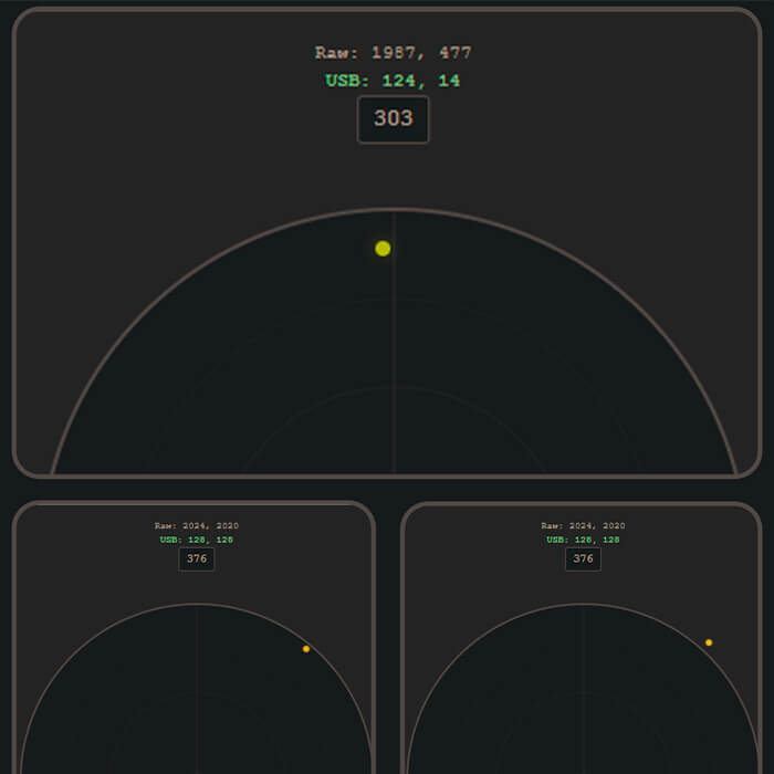
Move the thumbstick through the directions that showed undershooting during the Circularity test.
Identifying Issues (3/3)
Look for these common signs:
- • One or more directions don’t reach the edge of the circle.
- • Some directions require noticeably more force than others.
- • Diagonals don’t extend as far as expected.
- • Movement feels inconsistent between cardinal and diagonal directions.
Once you’ve identified the affected areas, continue to the next step.
Adjusting Low CER: Part 2
How to manually tune your cardinal directions and eliminate analog bottlenecking.
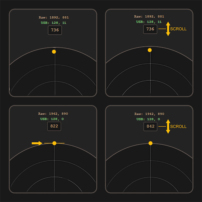
Value Tuning
To correct issues with the cardinal directions (Up, Down, Left, Right), follow these steps:
- • A. Push and hold the thumbstick fully in the direction that is failing to reach the edge of the circle.
- • B. Hover your mouse over the input box for that direction.
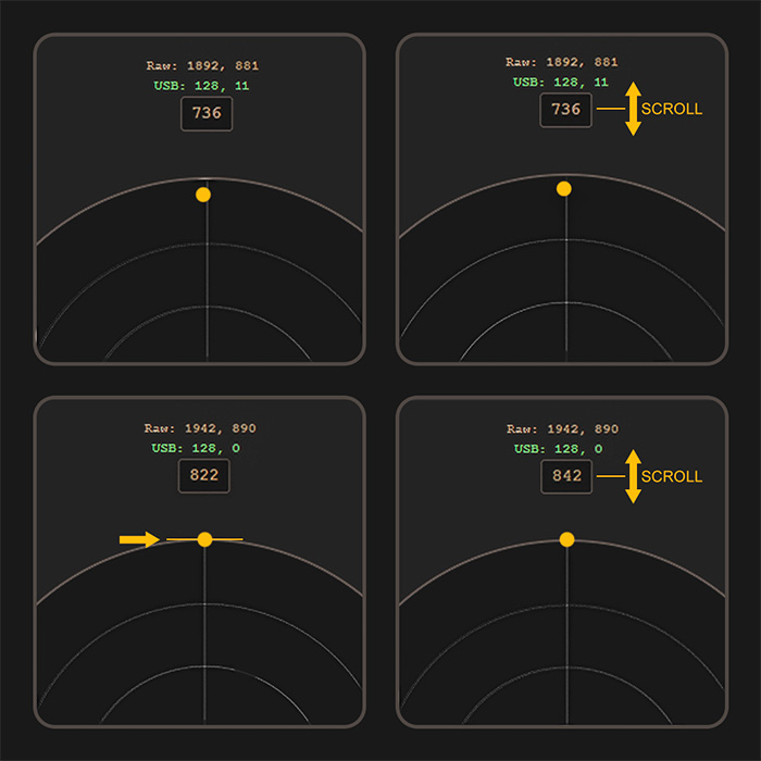
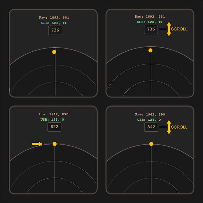
- • C. Scroll to adjust: While continuing to hold the thumbstick, use your mouse wheel to adjust the value. Depending on the direction, you may need to increase or decrease it.
Recommended Method
D. Safety Margin: Adjust the value gradually until the indicator just reaches the edge of the circle. Then increase it by approximately 20 units (about two scroll-wheel ticks) to provide a small safety margin.
The calibration tool prevents cardinal directions from extending beyond the circle, making it easy to accidentally stop too early. This method helps ensure the direction reaches full range consistently.
E. Settle & Retest: Rotate the thumbstick several times in full circles to allow the mechanism to settle. Then test the direction you adjusted again. If it still doesn’t reach the correct point, continue fine-tuning the value.
Circularity Verification
After adjusting the cardinal directions, save the calibration to the controller, return to Gamepad Tester, and run the Circularity Test again. In most cases, this should:
- • Bring your CER back into the recommended range.
- • Eliminate undershooting.
- • Improve in-game movement consistency.
If your CER is still too low or you continue to experience movement issues, proceed to one of the two adjustment methods below.
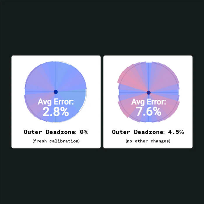
Increase the Outer Deadzone
Increase the Outer Deadzone by 0.5–1% at a time, up to a recommended maximum of 5%. Save the calibration and retest after each adjustment. This is the simplest solution and will resolve the issue for most users.
Keep in mind that increasing the Outer Deadzone reduces the physical thumbstick travel required to reach maximum input.
Note: Outer Deadzone settings may stack with in-game deadzone settings. If this resolves the issue and the controller still feels natural in-game, it’s perfectly fine to leave it at that value.
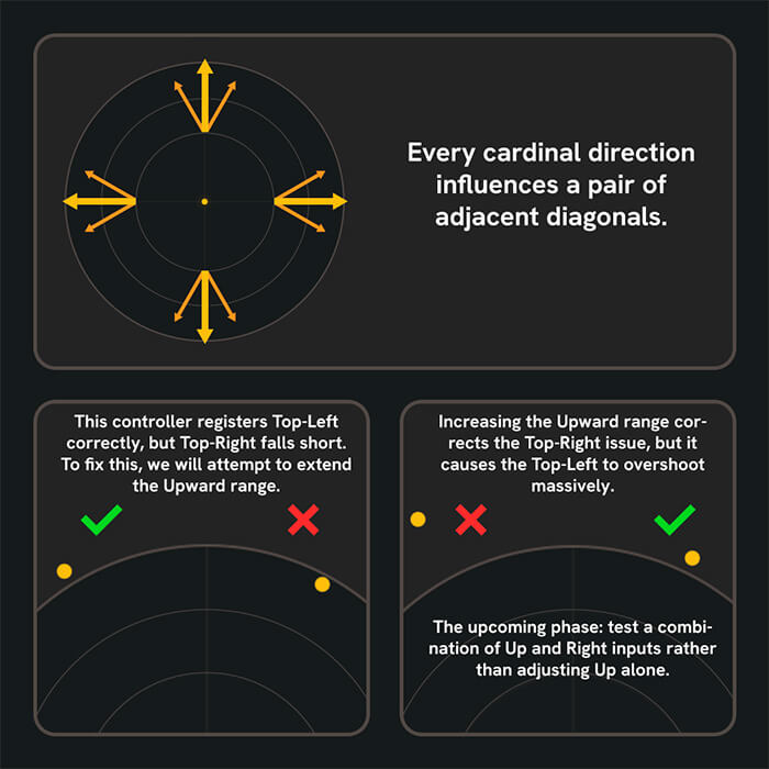
Manual Calibration Adjustment
- • Manually adjusting the cardinal directions changes the behavior of the surrounding diagonal directions. For example, moving the Up direction farther outward will also affect both Up-Left and Up-Right.
- • Each cardinal direction influences two adjacent diagonals, so improving one area may negatively affect another. Finding the right balance usually requires some trial and error.
If you aren’t satisfied with the results, you can always recalibrate the controller and start over.
My CER Seems High
Our target Circularity Error Rate (CER) is 6 – 9%, with every AIM MH5 controller tested before shipping.
A CER above this range doesn’t always indicate a problem. Many players won’t notice any difference even at 10–13%. However, if your controller feels inconsistent, recalibrate it and test again.
When recalibrating, apply steady, even pressure while rotating each thumbstick around its full range of motion. Keep in mind that your testing method affects the result. Uneven pressure, inconsistent movement, or repeating the test multiple times can all change the reported CER. Even rotating the controller to a different position may produce slightly different results.
If your CER remains unusually high after several calibration attempts, please contact Customer Support.
AIMCONTROLLERS IN-HOUSE SETTINGS
AIMCONTROLLERS IN-HOUSE SETTINGS
We calibrate each Marius Board in-house prior to shipping. Our settings aren’t universal or sacred, but if you want to get back to roughly how we shipped it, here’s our list of basic settings.
1mm instant click mode / Full-range analog mode
B1 – Triangle
B2 – Square
B3 – Circle
B4 – Cross